Showing posts with label underbody. Show all posts

2012-07-29

Replacing the fuel lines (4)

(backdated)

 Removing the Engine Fuel Pipes (2)

The easiest way to remove both engine fuel pipes is to remove partially remove the generator and the obstructing pipes and cables -- no need to touch the valve cover like I did earlier.

The belt loosens simply by twisting the tensioner device.

DSCN9658


The generator is attached with two bolts (Torx 45, Torx 50) in the front and a nut (10mm?) in the back. It's not necessary to completely remove the bottom bolt; when loosened, it'll work as a hinge over which the generator will swivel.

DSCN9664

Top-front bolt: 25 Nm
Bottom-front bolt: 50 Nm
Bracket-to-generator nut/bolt in the back: 25 Nm

Fitting in new underbody pipes

Dirt cleaned up from where the pipes will go. Some cavity wax was applied on the body too as a stop-gap measure. The whole paint job should really be redone & new chassis protector goo applied in the bottom.

DSCN9667


DSCN9675

Although the old pipes were flexible enough that I could pull them out in one piece, it wasn't possible to put the new hydraulic pipe, 1.0 mm wall thickness, in the same way. I decided to cut them in the front and reconnect them using compression fittings.

DSCN9677


This allowed me to bend the "final mile" outside the car. Unlike most of the plumbing, I'm actually satisfied with this piece.

DSCN9691


2012-07-21

Replacing the fuel lines (2)

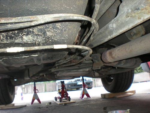
Removing the evap. emissions underbody pipe

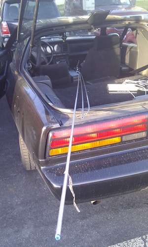
I started removing the underbody pipes by pulling out the evaporative emissions canister line. According to the service manual, this line only transfers fuel vapor from the tank, so there shouldn't be any fuel leaks when detaching the line. This turned out to be true. This is the longest of the three fuel lines, so I'd be able to get a proper measurement of the pipe as well.

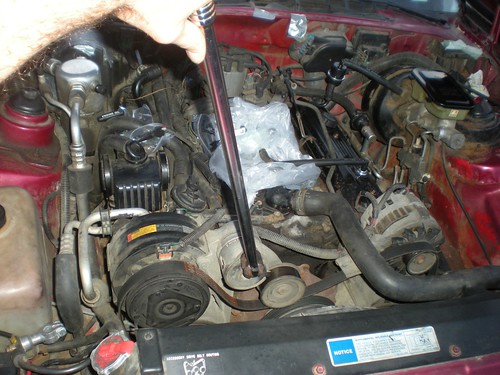
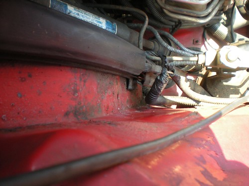
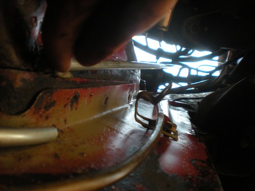
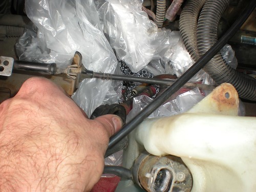
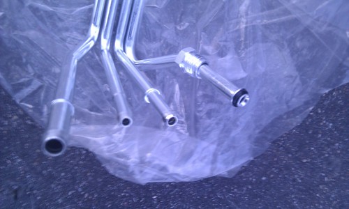
Engine room end of the evap. line:
DSCN9611

Bend points marked with tape:
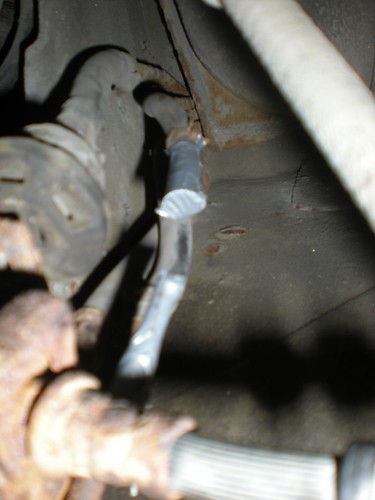
DSCN9615


DSCN9617


DSCN9620


One end detached:
DSCN9613


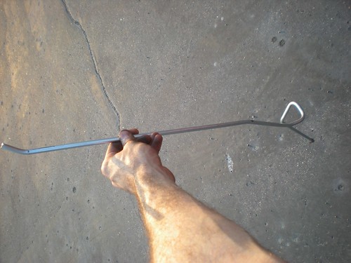
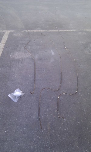
Both ends detached and closed with duct tape:
DSCN9623


After measuring the pipe, I found out the shocking truth -- the pipe is 330 cm long, but I had bought two 300 cm pipes! Luckily the hydraulic shop where I acquired the pipes agreed to change them to longer ones.

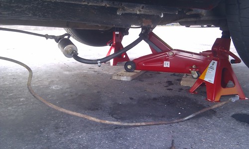
Removing rest of the underbody pipes


To depressurize the fuel system on the TBI engine *, it should be enough to turn off the engine and open the fuel filler cap. However, the feed and return lines still contain fuel, so removing them calls for some preparation and patience.

(* On the PFI (V6) and TPI engines, according to the service manual, you need to depressurize the system via the fuel pressure valve using "J 34730-1 Fuel Pressure Gage")

The hoses and the TBI engine's pipes contain some fuel as well.

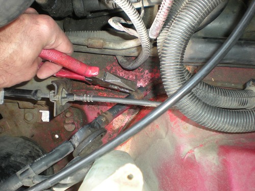
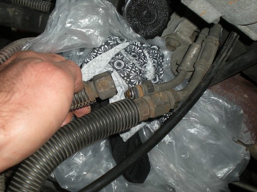
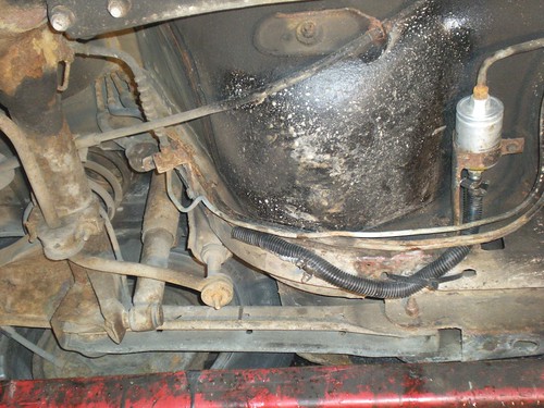
Disconnecting the fuel feed and return hoses from the engine:
DSCN9626

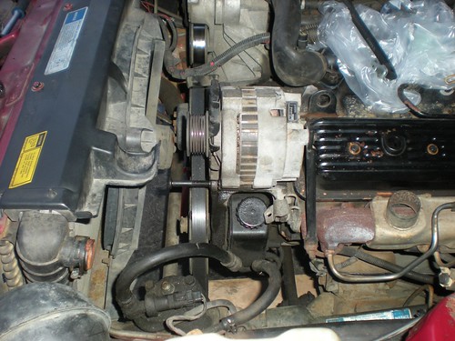
Engine room with feed and return hoses disconnected:
IMAG1101

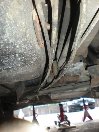
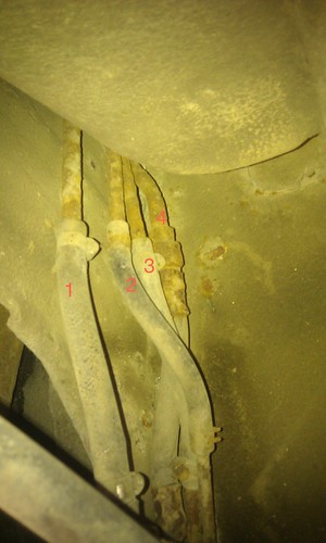
Pipes starting to come off.
Underbody pipes coming off

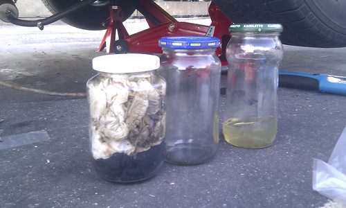
I collected the excess fuel to glass jars and eventually discarded them properly, wiping out spills as well as I could. Altogether there was maybe 0,3 - 0,5 liters of disposable fuel.
Gasoline


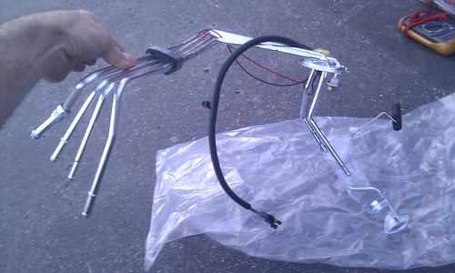
Victory, at last. The hoses and short pipe leading to the fuel level sender are still in the car.
Underbody pipes: fuel feed, return, evap.emissions

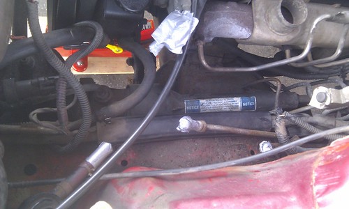
Fuel Filter Brain Damage

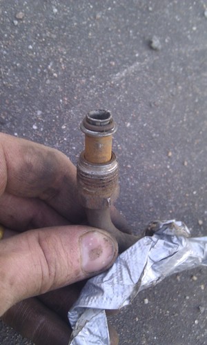
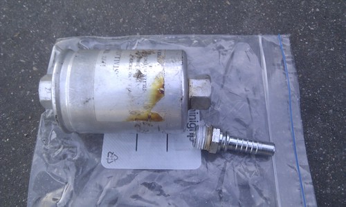
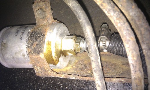
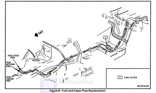
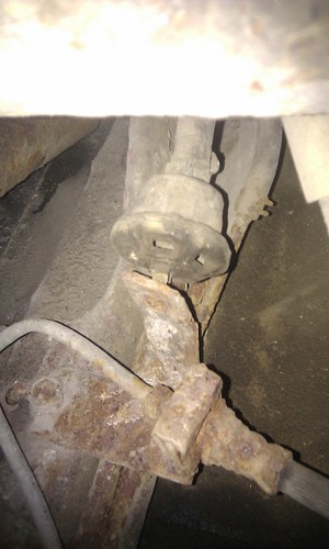
The fuel filter is normally attached to two flared pipe connectors like this:
IMAG1113


In my case, the part of the pipe leading to the filter intake side had been replaced with a hose, and a generic hose attachment was screwed onto the filter. That attachment did NOT have the flare & O-ring seal, but instead the mechanic had used this white sealing tape that I've previously seen in household water pipes.
DSCN9293

Old fuel filter and adapter on filter intake side

Hose adapter on old fuel filter's intake side, with leaked silicone(?) sealing tape


The seal had been leaking constantly just a little bit, as the stained area on the filter shows. This was probably (hopefully) the source for the gasoline smell I'd been noticing in the car.

IMAG1062


Whoever did this.... not nice.

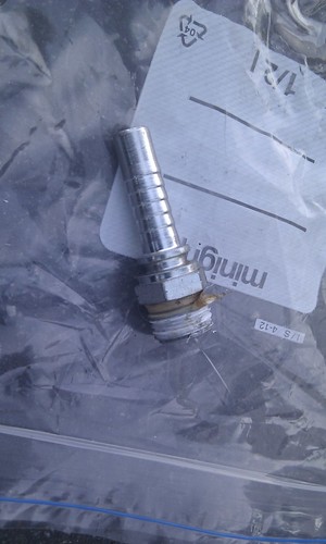
I believe the correct way to fix the broken pipe would have been to use one of these:

(ribetautoparts.com)

i.e. a steel pipe with the correct GM-style flared connector already present. A repair kit like this goes for €25 - €35 in this city.


2012-07-15

Replacing the fuel lines (1)

As is obvious from the photos, the rusty fuel lines are my top concern on this car. They look as if they're about to disintegrate any moment, and although there's no visible leaks, sometimes it smells of gasoline inside the car. Part of the feeder line had already been replaced with a hose, probably when the filter was changed.

While replacing the lines, I'm also trying to use E85 (ethanol fuel) compatible parts, so that it's possible to run on cheaper (or, just existent...) fuel in the future. Stainless steel, and hoses and O-rings specified for gasoline and ethanol should be sufficient.

Pipes

The pipe layout looks like this:

Pontiac Firebird underbody fuel lines


There are 3 underbody fuel pipes:
  • Fuel feed to the TBI unit (outside diameter 9,5 mm)
  • Fuel return from the TBI unit (outside diameter 8 mm)
  • Fuel return from the evaporative emissions canister (outside diameter 8 mm)

For the feed pipe, I've purchased 4 m of 10mm outside diameter steel pipe w/ 1,5 mm wall thickness.

For the return pipes, two 3m 330 cm pieces of 8mm outside diameter steel pipe w/ 1,0 mm wall thickness.

Total cost for the pipes was € 89,35.

IMAG1086

Fuel Level Sending Unit


In the tank end, the pipes form part of a device called the Fuel Level Sending Unit (or Assembly) that also holds the fuel pump and fuel level sensor. The current one is in as terrible condition as the underbody pipes, so I've acquired a new one.  The unit is a Spectra Premium FG20A from RockAuto, cost € 100.46 ($127). Unfortunately I don't know what material this unit is, i.e. whether it's E85-compatible. At least it's new.


New Fuel Level Sending Assembly
Fuel Level Sending Unit
New Fuel Level Sending Assembly
Fuel Level Sending Unit - hose connectors


Counting from the left:
  1. Vent (breather) pipe (?)
  2. Evaporative Emission System  line (?)
  3. TBI return line (?)
  4. Fuel feed line


IMAG1040
This is how the current sending unit's pipe ends look like.

The hose in the leftmost pipe connects to this mushroom-like device.

IMAG1060

2012-05-13

More underbody horrors


The hatch door leaks.


Left rear wheel

Left rear wheel

Right rear wheel


Part of the steering, I believe