2012-08-22

AN hoses and fittings for the fuel lines

[backdated]

This stuff connects the long, underbody fuel lines to the short pipes mounted on the engine.

Apart from the the fuel filter and TBI adapters (the black aluminum parts), the components were acquired from Dunlop Hiflex. These guys were quite helpful, I just gave them my crappy pencil drawings and they assembled the correct hoses and fittings for me on the spot.


DSCN9745

Assembled:

DSCN9751 - Version 2

Fuel feed line: top right-to-left, counter clock wise
  • Vinyl(?) gasket, replaced w/ Teflon
  • Aluminum adapter: TBI (14x1.25mm) to AN-6
  • Hydraulic hose assembly: AN-6 / ??mm teflon hose / AN-8
  • Fuel filter: AN-8 / AN-8
  • AN-8 to ?? thread adapter 
  • Compression fitting for 10mm pipe w/ ?? thread
  • 2x Compression fittings for 10mm pipe
  • Compression fitting for 10mm pipe, barb fitting for 10mm hose
Fuel return line: bottom right-to-left, counter clock wise
  • Vinyl(?) gasket, replaced w/ Teflon
  • Aluminum adpater: TBI (12x1.25mm) to AN-6
  • Hydraulic hose assembly: AN-6 / ??mm teflon hose / ?? thread
  • Compression fitting for 8mm pipe w/ ?? thread
  • 2x Compression fittings for 8mm pipe
  • Compression fittings for 8mm pipe, barb fitting for ??mm hose


2012-08-21

Torque settings

Generator
  • Top-front bolt: 25 Nm
  • Bottom-front bolt: 50 Nm
  • Bracket-to-generator nut/bolt in the back: 25 Nm
Thermostat housing
  •  LB9 and L98: 34 Nm (25 lb. ft.), 
  •  L03: 28 Nm (21 lb. ft.).
  •  LHO: 21 Nm (15 lb.ft.).
Valve rocker cover
  •  11 Nm (95 lb in)
Throttle Body
  • TBI attaching bolts: 22 Nm (16 lb ft)
  • Fuel inlet/outlet nut (original, screw onto TBI unit - replaced by aluminum adapters): 
    • inlet nut 40 Nm  (30 lb ft)
    • outlet 29 Nm (21 lb ft)
  • Fuel line nuts (original, attache pipesto in-/outlet nuts - replaced by AN-6 fittings ): 
    • 27 Nm (20 lb ft)
  • I'm not sure the aluminum adapters and teflon gaskets can handle the same tightening torque as the original (steel?) nuts.


2012-08-11

Cheap aluminum pipe benders

Avoid them at all costs.

I broke _two_ of these in one day bending 10x1.5 mm zinc-plated steel pipe. It did handle 8x1.0mm pipe well.

This piece of failure is imported/branded by IKH and sold by Motonet for € 10,90.

IMAG1247


Russell 640813, 640803 TBI fuel line adapters

After a logistical hassle that shouldn't happen in 2012, I got the necessary fuel line adapters for the GM (Rochester) TBI unit:
  • Russell 640813: male 14x1.25 mm (14 mm thread w/ 1.25 mm pitch) to male AN-6
  • Russell 640803: male 142x1.25 mm (12 mm thread w/ 1.25 mm pitch) to male AN-6
DSCN9753

However, the hydraulic shop informed me that the white seals these fittings come with are a kind of vinyl material that isn't E85 compatible. I'll need to get replacements for those, apparently out of Teflon (PTFE).

They're not O-rings, but a straight cylindrical shape instead.

DSCN9766


The original fittings have a wedge that holds the seal in place, and the original seals have a slightly conical(?) shape that makes them snap onto the end of the fitting.

Tiivistekeskus didn't stock this kind of seal, and their sales person wasn't very optimistic about finding one either. Apparently they don't have verified information about combined gasoline and E85 compatibility of their materials, and weren't prepared to make wild guesses either. They could "lathe" custom PTFE (Teflon) gaskets according to measurements, at an approximate price or € 50 apiece, though.

Seal dimensions:


All measurements are in mm.

2012-08-01

Golan fuel filter aqcuired

(backdated)

The Golan fuel filter arrived in the mail.

DSCN9700
According to the instruction sheet, the filter can be used in a "racing", or bypass, configuration in addition to the standard one simply by reversing the order of the internal components (or turning the whole filter around). Apparently in this configuration the fuel pressure would force (part of?) the fuel to travel around the actual filter element.

I was surprised to find that the filter shipped in this reverse configuration. If I hadn't taken it apart, I might have installed it the wrong way around, thereby allowing impurities to reach the fuel injectors. Not fun.

The flow direction arrows on the filter are opposite from those in the documentation, so that could explain the weird configuration.

DSCN9702


Also, the filter element is bent:

DSCN9708

Gollan installation manual:

DSCN9772


2012-07-30

E85 Fuel Filter Choices

The stock fuel filter also uses those pesky GM flared connectors, so if I wanted to use one, I'd have to use those repair pipe kits on both sides of the filter and connect them up with some ugly compression fittings - not a very clean solution. Also, there are no guarantees that the stock filter (which would have been a Wix 33481) can withstand E85 fuel.

According to the service manual,
[a] fifteen micron fuel filter is used in the fuel feed pipe ahead of the fuel injection system and mounted directly in front of the rear axle. The filter housing is constructed of steel with threaded Fittings at both ends. The fittings are sealed with O-rings. The filter element is made of paper, and is designed to trap particles in the fuel that may damage the injection system.
This should apply to all engines (3.1L, TBI, TPI).

So, at least a 15 micron filter is required, and it should somehow connect to the AN plumbing that will be used at the TBI unit. A reasonable price and availability of replacement filters / elements would also be nice. The Wix filter is even rated at 4 micron.


I actually sacrificed two days from my life trying to find a suitable filter. The local supplier's knowledge and/or motivation on this matter proved practically non-existent, and the manufacturer's specs aren't always clear either.

The Fuelab 8183X series have male AN fittings and use a disposable, 6 micron, fiberglass, E85-compatible element. This would seem optimal, but a bit pricey. They go for around €140 at turbozentrum.de, and replacement elements are about €33

Summit Racing sells filters by Russell performance with 10 micron paper elements. Filters go for around $75 (about €130 including delivery & customs), replacement elements for about $23. Only Summit and a random magazine article claim that they're E85 compatible; Russell's own web pages or catalogs don't mention it at all.

The Magnafuel inline filters claim Ethanol compatibility, but the marketing text is ambiguous. The filters have metal elements down to 25 micron, and the 10 micron model has a paper element. The chapter where the compatibility claim is made refers to a "[choice] between 75 and 25 micron filters", and the 10 micro model only appears in the product listing. Their PDF catalog has the same text, but doesn't list the 10 micron filter at all. One could read this either way; I'd rather not reward such ambiguity.

The SX Performance 41002 is available for $91 and includes a 10 micron paper element, but the brand seems a bit obscure -- how long will replacement elements be available?

AES Performance sells an element w/ NPT fittings for $50 on eBay. Cheap, but likewise a small company.

Finally, I went for a Golan "40 - Large" filter,  $85 from Jay Racing. Express Mail International shipping was $59,40, total w/ VAT & customs will likely be around €150 ($185). It has AN-8 fittings (AN-6 was out of stock) and a washable metal element, and the company's propaganda was convincing enough. Here's one installation (scroll down to bottom), and some people having (scary) issues w/ the Golan filter. Hopefully these are just, eh, individual cases.

There's some generic talk on E85 filters here and here.

Also, there are 40 micron filters available for $19 at anfittingsdirect.com with a cleanable, reusable bronze element, suitable for pre-pump use.

2012-07-29

Replacing the fuel lines (4)

(backdated)

 Removing the Engine Fuel Pipes (2)

The easiest way to remove both engine fuel pipes is to remove partially remove the generator and the obstructing pipes and cables -- no need to touch the valve cover like I did earlier.

The belt loosens simply by twisting the tensioner device.

DSCN9658


The generator is attached with two bolts (Torx 45, Torx 50) in the front and a nut (10mm?) in the back. It's not necessary to completely remove the bottom bolt; when loosened, it'll work as a hinge over which the generator will swivel.

DSCN9664

Top-front bolt: 25 Nm
Bottom-front bolt: 50 Nm
Bracket-to-generator nut/bolt in the back: 25 Nm

Fitting in new underbody pipes

Dirt cleaned up from where the pipes will go. Some cavity wax was applied on the body too as a stop-gap measure. The whole paint job should really be redone & new chassis protector goo applied in the bottom.

DSCN9667


DSCN9675

Although the old pipes were flexible enough that I could pull them out in one piece, it wasn't possible to put the new hydraulic pipe, 1.0 mm wall thickness, in the same way. I decided to cut them in the front and reconnect them using compression fittings.

DSCN9677


This allowed me to bend the "final mile" outside the car. Unlike most of the plumbing, I'm actually satisfied with this piece.

DSCN9691


2012-07-25

Replacing the fuel lines (3)

Pipe Fittings


I put the carriage before the horse. Getting compatible fittings, adapters etc. should have come first.

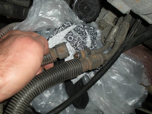
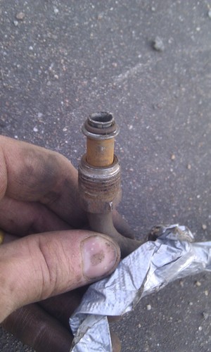
My original plan was to aim for maximum compatibility & originality -- simply recreating the car's original configuration, but with E85-compatible materials. This would mean replacing the body-to-engine feed and return hoses in the engine room with identical parts, getting the flared "screw" fittings fabricated onto the pipe ends, and replacing all O-rings. It turns out this wasn't so simple after all.

Fuel feed line - underbody pipe - engine bay end
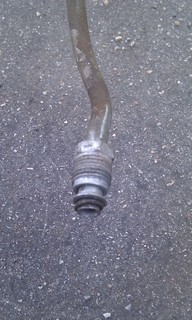
Apparently the "flared end + thread" fitting used in the fuel lines is a GM-specific thing, and fabricating it onto a raw piece of pipe requires a special tool.

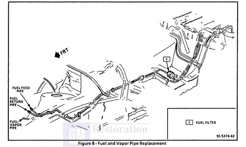
This fitting is found in
  • Fuel feed line, 
    • between level sender assy and rear body pipe
    • between rear body pipe and fuel filter intake
    • between fuel filter exit and front body pipe
    • between front body pipe and body-to-engine hose
    • between body-to-engine hose and engine pipe
    • between engine pipe and TBI unit (adapter)
  • Fuel return line,
    • between TBI unit (adapter) and engine pipe
    • between engine pipe and body-to-engine hose
    • between body-to-engine hose and body pipe
All other hose-pipe fittings use simple clamps.

I've queried American ServiceSouth West TradeUS PartsMetro AutoSpecialty Engineering and Hydromarket whether it was possible to fabricate the male end to an existing pipe, or if  any kind of adapters to either the male or female side of this attachment are available. No-one seems to even know about such adapters, and the the repair shops don't have the equipment to create the flared pipe ends either.
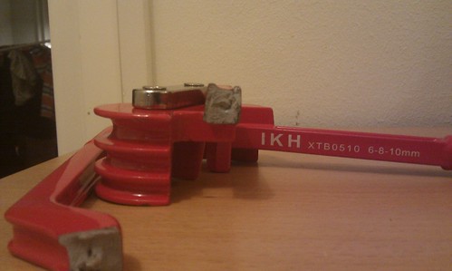
For the record, a GM Fuel Line Flaring Tool Kit goes for between $203 and $360 in the US, so I'm surprised that even reputable shops don't have them.

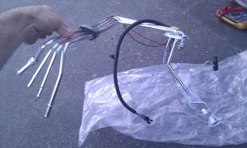
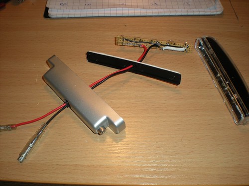
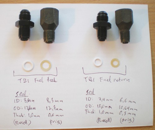
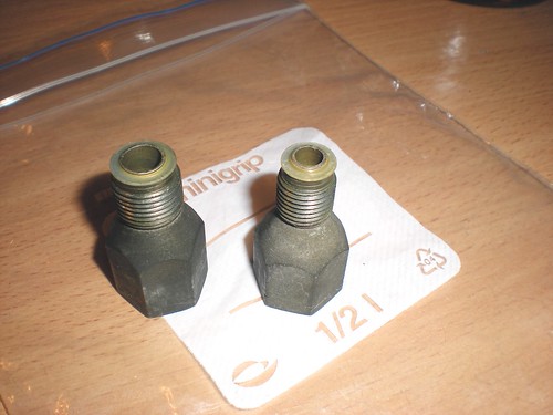
The TBI Fuel Pipe Fitting

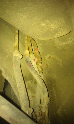
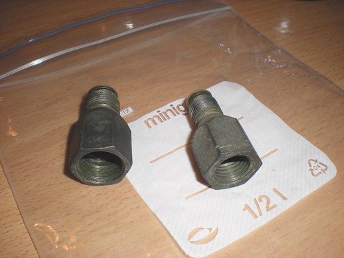
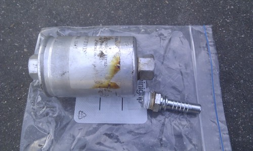
Finally, I noticed that the connectors at the end of the Throttle Body are different. This will at least allow me to attach something to the throttle body. The pipes that run along the engine block do have the GM-specific connectors in both ends, but they attach to the TBI via these adapters:

Original TBI fuel line fitting adapters

Original TBI fuel line fitting adapters


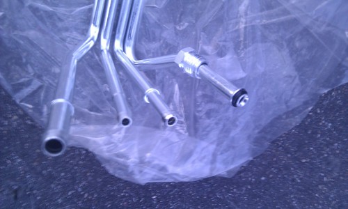
Left: fuel feed pipe adapter. The male thread is apparently an M14x1.25 (measured diameter 13.7 mm, thread pitch 1.25 mm)

Right: fuel return pipe adapter. This seems to be an M12x12.5 thread (measured diameter: 11,8 mm, thread pitch 1.25 mm).

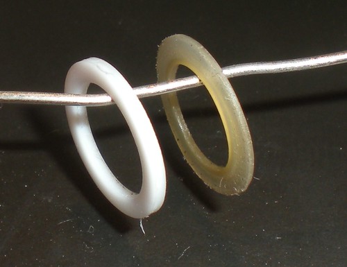
Notice the white plastic(?) ring at the end of each adapter. They probably work as seals, so simply screwing an adapter with the same thread, but without the seal, wouldn't suffice.

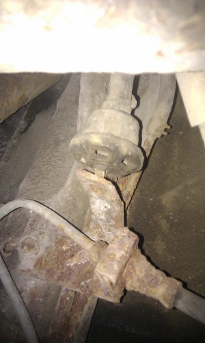
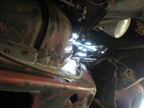
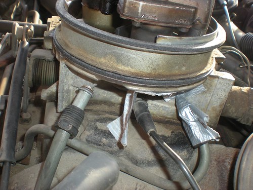
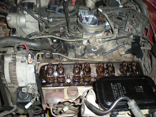
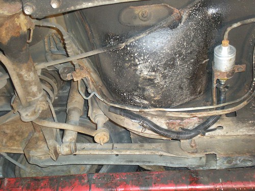
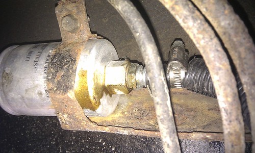
The behind of the Throttle Body, w/o the adapters. Fuel feed pipe on the left (exposed), fuel return pipe on the right (covered in duct tape):

DSCN9635


IMAG1128


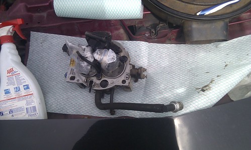
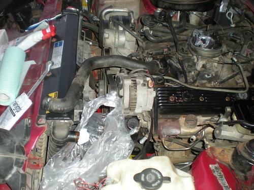
It was impossible to get useful measurements of the available space around the ports, so after carefully removing dirt from around the TBI unit, I screwed it off from the intake manifold and took it shopping. It's attached with three bolts, left, right and front.

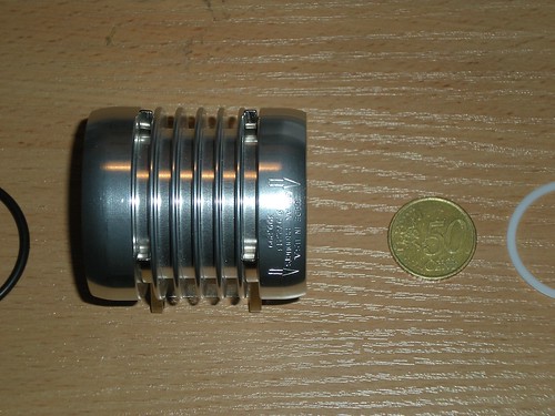
The TBI unit removed:

TBI unit from a V8 305 TBI


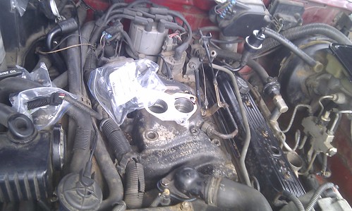
The intake manifold exposed. Engine oil was coming out of the TBI bolt hole on the driver's side. In this pic I had also removed the fuel return pipe, and the fuel feed pipe is loose on the right side (details below).

V8 305 TBI with the TBI unit removed


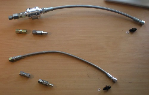
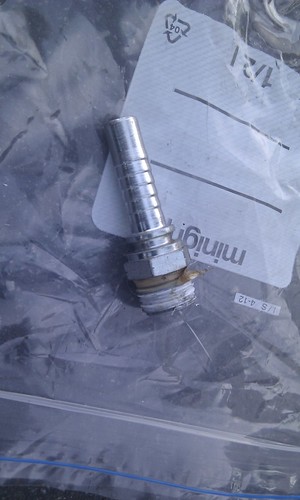
After a few iteration around the shops, a helpful sales rep at US Parts managed to find adapters that fit the female threads in the Throttle Body. The adapters then let you connect AN system hose fittings and hoses, specifically size AN-6, which means a hose inner diameter of 6 * 1/16" = 3/8" = 9.525 mm. The original fuel feed line was probably 3/8" as well.

The magical pair of adapters in question is one of Russell 640813 and 640803 (black, anodized) or 640800 and 640810 (blue, nickel plated). The black ones were ordered and should arrive in 1-2 weeks.

More on pipe fittings (Wikipedia): Compression_fittings, Flare_fitting, AN_thread, National_pipe_thread

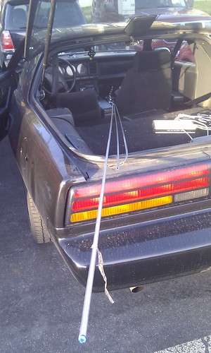
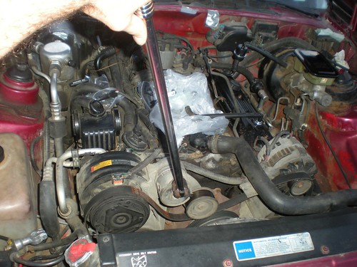
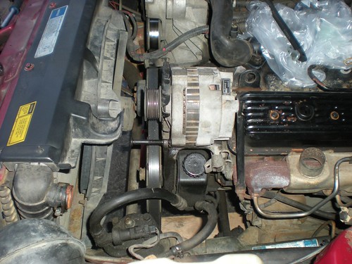
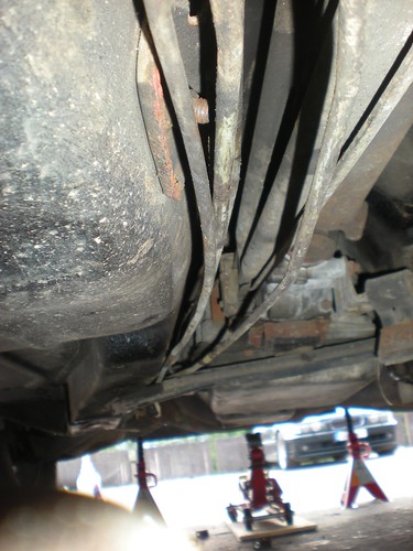
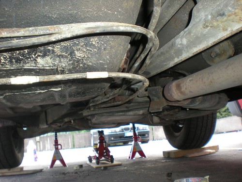
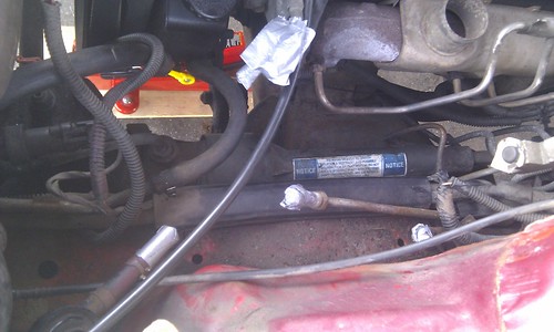
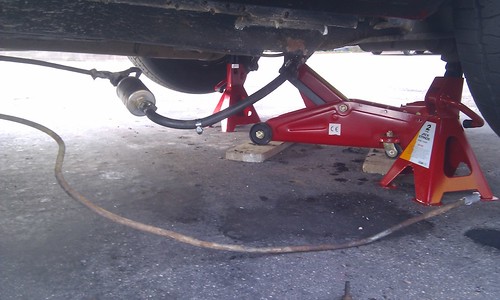
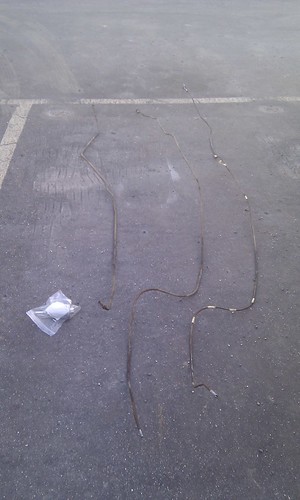
Removing the Engine Fuel Pipes (1)

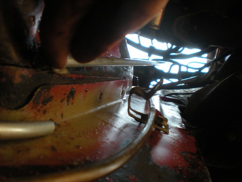
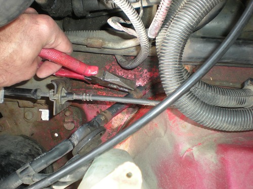
Since I'll be connecting hoses directly to the back of the TBI, the engine fuel feed and return pipes are redundant. Due to their shape and the flared ends, the pipes can't simply be pulled out though. The easiest way to remove them would be to split them in half with a pipe cutter, but I simply can't bring myself to destroying original components that are still in fine usable condition. So, we'll disassemble parts until they come out.

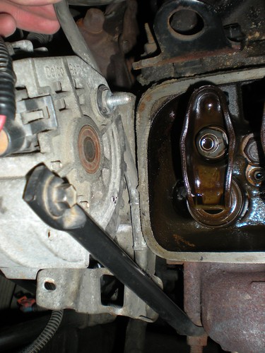
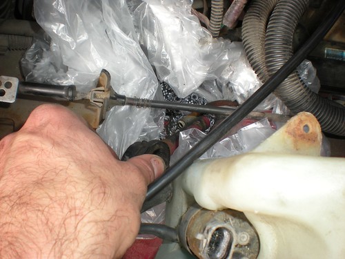
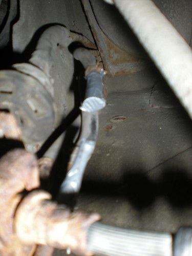
To get the fuel return pipe out, I had to remove
  • PCV filter and hose (attach to the driver's side valve cover)
  • Brake booster vacuum pipe (front of TBI / intake plenum)
  • The 3 throttle cables attached to the side of the TBI (throttle pedal, cruise control and ??)
  • Positive cable at the back of the charger
  • Upper coolant hose
  • Driver's side valve cover
DSCN9640

      DSCN9643

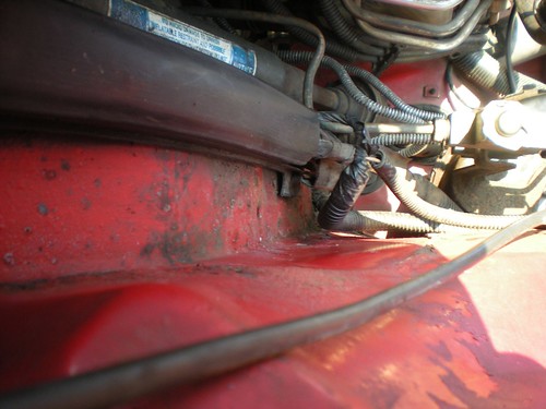
      Even then, it's too tight between the charger and the rocker box to get the thicker fuel feed pipe out. There are some nasty scratches on the pipe already.

      DSCN9646

      ... more to follow.

      2012-07-21

      Replacing the fuel lines (2)

      Removing the evap. emissions underbody pipe

      I started removing the underbody pipes by pulling out the evaporative emissions canister line. According to the service manual, this line only transfers fuel vapor from the tank, so there shouldn't be any fuel leaks when detaching the line. This turned out to be true. This is the longest of the three fuel lines, so I'd be able to get a proper measurement of the pipe as well.

      Engine room end of the evap. line:
      DSCN9611

      Bend points marked with tape:
      DSCN9615


      DSCN9617


      DSCN9620


      One end detached:
      DSCN9613


      Both ends detached and closed with duct tape:
      DSCN9623


      After measuring the pipe, I found out the shocking truth -- the pipe is 330 cm long, but I had bought two 300 cm pipes! Luckily the hydraulic shop where I acquired the pipes agreed to change them to longer ones.

      Removing rest of the underbody pipes


      To depressurize the fuel system on the TBI engine *, it should be enough to turn off the engine and open the fuel filler cap. However, the feed and return lines still contain fuel, so removing them calls for some preparation and patience.

      (* On the PFI (V6) and TPI engines, according to the service manual, you need to depressurize the system via the fuel pressure valve using "J 34730-1 Fuel Pressure Gage")

      The hoses and the TBI engine's pipes contain some fuel as well.

      Disconnecting the fuel feed and return hoses from the engine:
      DSCN9626

      Engine room with feed and return hoses disconnected:
      IMAG1101

      Pipes starting to come off.
      Underbody pipes coming off

      I collected the excess fuel to glass jars and eventually discarded them properly, wiping out spills as well as I could. Altogether there was maybe 0,3 - 0,5 liters of disposable fuel.
      Gasoline


      Victory, at last. The hoses and short pipe leading to the fuel level sender are still in the car.
      Underbody pipes: fuel feed, return, evap.emissions

      Fuel Filter Brain Damage

      The fuel filter is normally attached to two flared pipe connectors like this:
      IMAG1113


      In my case, the part of the pipe leading to the filter intake side had been replaced with a hose, and a generic hose attachment was screwed onto the filter. That attachment did NOT have the flare & O-ring seal, but instead the mechanic had used this white sealing tape that I've previously seen in household water pipes.
      DSCN9293

      Old fuel filter and adapter on filter intake side

      Hose adapter on old fuel filter's intake side, with leaked silicone(?) sealing tape


      The seal had been leaking constantly just a little bit, as the stained area on the filter shows. This was probably (hopefully) the source for the gasoline smell I'd been noticing in the car.

      IMAG1062


      Whoever did this.... not nice.

      I believe the correct way to fix the broken pipe would have been to use one of these:

      (ribetautoparts.com)

      i.e. a steel pipe with the correct GM-style flared connector already present. A repair kit like this goes for €25 - €35 in this city.


      2012-07-15

      Replacing the fuel lines (1)

      As is obvious from the photos, the rusty fuel lines are my top concern on this car. They look as if they're about to disintegrate any moment, and although there's no visible leaks, sometimes it smells of gasoline inside the car. Part of the feeder line had already been replaced with a hose, probably when the filter was changed.

      While replacing the lines, I'm also trying to use E85 (ethanol fuel) compatible parts, so that it's possible to run on cheaper (or, just existent...) fuel in the future. Stainless steel, and hoses and O-rings specified for gasoline and ethanol should be sufficient.

      Pipes

      The pipe layout looks like this:

      Pontiac Firebird underbody fuel lines


      There are 3 underbody fuel pipes:
      • Fuel feed to the TBI unit (outside diameter 9,5 mm)
      • Fuel return from the TBI unit (outside diameter 8 mm)
      • Fuel return from the evaporative emissions canister (outside diameter 8 mm)

      For the feed pipe, I've purchased 4 m of 10mm outside diameter steel pipe w/ 1,5 mm wall thickness.

      For the return pipes, two 3m 330 cm pieces of 8mm outside diameter steel pipe w/ 1,0 mm wall thickness.

      Total cost for the pipes was € 89,35.

      IMAG1086

      Fuel Level Sending Unit


      In the tank end, the pipes form part of a device called the Fuel Level Sending Unit (or Assembly) that also holds the fuel pump and fuel level sensor. The current one is in as terrible condition as the underbody pipes, so I've acquired a new one.  The unit is a Spectra Premium FG20A from RockAuto, cost € 100.46 ($127). Unfortunately I don't know what material this unit is, i.e. whether it's E85-compatible. At least it's new.


      New Fuel Level Sending Assembly
      Fuel Level Sending Unit
      New Fuel Level Sending Assembly
      Fuel Level Sending Unit - hose connectors


      Counting from the left:
      1. Vent (breather) pipe (?)
      2. Evaporative Emission System  line (?)
      3. TBI return line (?)
      4. Fuel feed line


      IMAG1040
      This is how the current sending unit's pipe ends look like.

      The hose in the leftmost pipe connects to this mushroom-like device.

      IMAG1060

      2012-07-13

      Fixing an SJ-269SE LED Daytime light


      This is how it should look like (thepontiactransampage.com)
      Normally, the Firebird's front turn signals double as "parking" / daytime running lights, but on this side of the Atlantic, these lights must be white. This rule is enforced quite randomly though; this time the car's previous owner got the short straw, and had to install these ill-suited aftermarket DRLs.

      Of course, one of the aftermarket lamps had to fail. As Mr. Previous Owner wasn't one to waste his time on storing receipts or other documentation, warranty replacement wasn't an option either. The device itself is insanely simple (apparently a power regulator, some resistors and 5 LEDs), but (on account of ECE standards compliance?), they tend to cost around 50-100 eur.

      Hence, the need to fix the MyCARR SJ-269SE, in as ECE-R7 compliant a way as possible, and to document it here. The device's conformance inspection report says it should emit 30 cd of light with about 20-30 degree horiz./vert/. angle, i.e. 6 cd per LED.

      I tested three different LEDs:
      Of these three, the latter one is a nearly identical match for intensity, emission angle and color tone. The flat ones in the pic are the unit's original LEDs, the 33BCWK5A is the tall one in the middle.


      I later found what looks very much like the original LED, http://uk.rs-online.com/web/p/visible-led/7134876/

        Three of the original LEDs were still working, and as they fit the reflector better than the common bulb type, I kept those in the center.

        They're connected in series with current limiting resitors, in two parallel groups, like this


        (+)-----------+--------------\
        14V           |              |
                    R1 =           R2 =
                    52 ohm         270 ohm
                      |              |
                     _|_            _|_              
                     \ /            \ /
                     ---            ---
                      |              |
                     _|_            _|_              
                     \ /            \ /
                     ---            ---
                      |              |
                     _|_             |
                     \ /             |
                     ---             |
                      |              |
        (-)-----------+--------------/

                    orig.           new
                    LEDs            LEDs

              14V - (3 * 3,8V)
        R1 = ------------------  = 52 ohm
                   0,05 A


              14V - (2 * 3,7V)
        R2 = ------------------  = 246,66.. ohm
                   0,03 A

        The LEDs' voltages and max. currents (3,8 V / 50 mA and 3,7 V / 30 mA) come from the datasheets and seller's specs.

        After experimenting, I ended up with 270 ohm for R2 to get similar brightness from both LED types.

        There's more on LED circuits at http://www.kpsec.freeuk.com/components/led.htm


        DSCN9606

        DSCN9607


        I've yet to test how it looks like next to the original light.